这是一个英国的vhdl硬件设计Assignment代写
1 Task one Full Adder
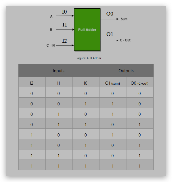
Full Adder is the adder which adds three inputs and produces two outputs. The first two inputs
are A and B and the third input is an input carry as C-IN. The output carry is designated as C
OUT and the normal output is designated as S which is SUM.
A full adder logic is designed in such a manner that can take eight inputs together to create a
byte-wide adder and cascade the carry bit from one adder to the another.
4 to 2 Encoder
An Encoder is a combinational circuit that performs the reverse operation of Decoder. It has
maximum of 2n input lines and ‘n’ output lines. It will produce a binary code equivalent to the
input, which is active High. Therefore, the encoder encodes 2n input lines with ‘n’ bits. It is optional
to represent the enable signal in encoders.
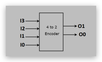
Let 4 to 2 Encoder has four inputs I3, I2, I1 & I0 and two outputs O1 & O0. The block diagram of
4 to 2 Encoder is shown in the following figure.
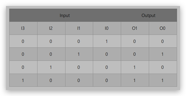
At any time, only one of these four inputs can be ‘1’ in order to get the respective binary code
at the output. The Truth table of 4 to 2 encoder is shown below.
Create a VHDL design and testbench code for the below specification? [40 Marks]
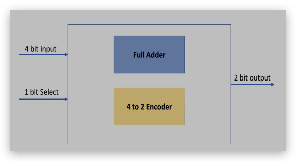
Use 4-bit input. 1-bit SEL decides to output the result of Full Adder or Encoder
Note: For the adder ignore the MSB from the input
2 Task two
8-bit Adder / Subtractor
A binary parallel adder is a digital function that produces arithmetic sum of two binary numbers
in parallel. It consists of full-adder combinational arrangement thus, the output carry from one
full adder connected to the input carry of next full- adder. In 8-bit binary parallel adder-subtractor
there are eight full adders connected in a parallel way. In this circuit the addition and subtraction
are done through the same circuit